Reimagining Stonehenge: The Roof Theory
by František Hájek
In the context of solving the mystery of the Stone Monument, the question of whether it originally had a roof has arisen before. This question itself is relatively old, in 1937, A. Vayson de Pradenne [1] proposed a hypothetical conical wooden roof design. Subsequently, designs by S. Ewbank, B. Bedlam, and G. Carter were published [2, 3, 4], but these were not accepted because, but not only, the designs did not correspond to Neolithic technologies and tools, nor were they entirely compatible with the characteristics of the stone support system.
Today, the accepted archaeological literature does not consider a roof, stating that no remains of it have been found [5]. However, the lack of physical evidence for a roof should not be used as evidence that there was no roof. The gradual decay of an organic structure due to weathering, combined with years of human interference, would not necessarily leave any evidence to be found. To address this mystery, we need to assess:
- whether the stones themselves had the properties and capabilities to act as a roof support, and
- whether the destruction of the original object could be attributed to the presence of a roof.
Both questions are the main subject of this research.
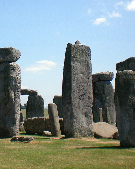
The Ruin

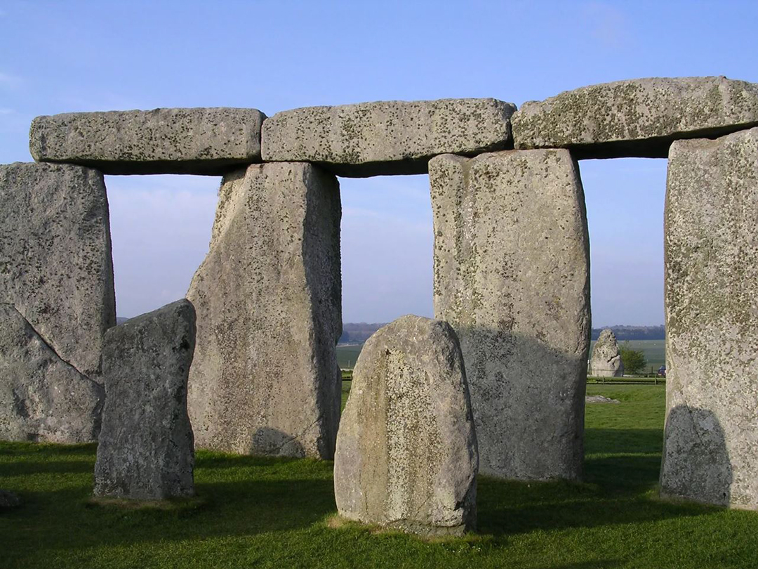
Today, the Stone Monument is an incomplete ruin (Fig. 1) consisting of megalithic stones [10]. However, it is widely accepted that it was originally a completed structure [6, 7, 13]. Archaeological surveys have shown that in its penultimate stage of development [5, 6, 7, 15], it consisted of several different elements, which ultimately formed:
- Two groups of massive uprights connected by lintels, called the Sarsen Circle (SC) and Sarsen Horseshoe (SH).
- Two groups of bluestones, consisting of significantly smaller free-standing pillars, called the Bluestone Circle (BC) and Bluestone Horseshoe (BH).
In addition, there was a standalone sandstone block called the Altar Stone at the centre of the monument.
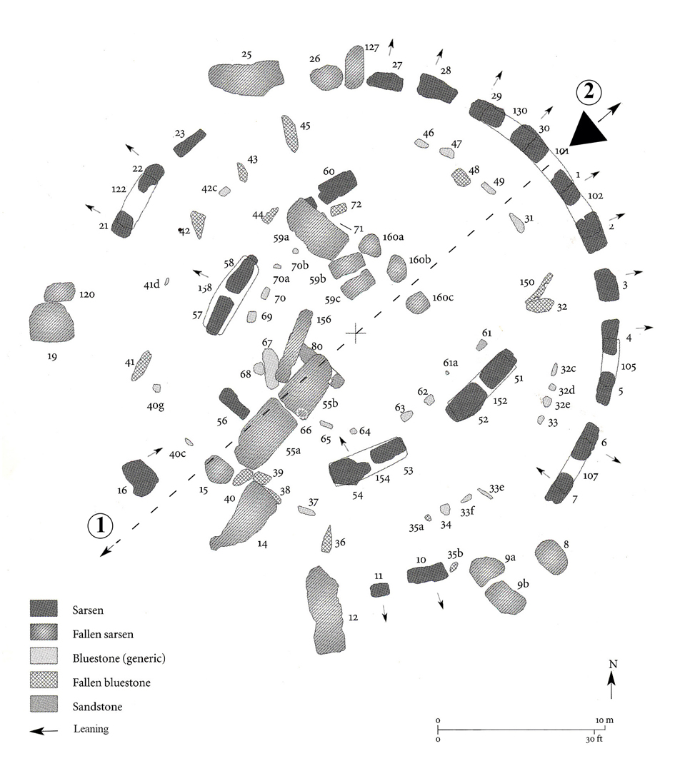
From the current state of the ruin (Fig. 2), it is evident that the SC group formed a perimeter around the Stone Monument, with the SH group inside it, and the BC and BH groups positioned within their corresponding sarsen groups. The orientation of the Stone Monument is unique – all of the stones were arranged symmetrically along the Stone Monument‘s astronomical axis – a virtual line connecting the sunset on the winter solstice and the sunrise on the summer solstice [6, 14]. This line passed through the gap between uprights 30 and 1 to the northeast and uprights 15 and 16 to the southwest, continuing along the axis of the main access road.
All groups were located inside the so-called Rectangle of Station Stones, whose circumferential links were also of astronomical significance [14, 17], the shorter ones having the same orientation as the axis of the monument. The centre of SC and thus the entire Stone Monument formed the intersection of diagonals of the Rectangle of Station Stones. The astronomical properties of the rectangle and the intersection of its diagonals indicate that the Station Stones predate the Sarsen Circle and were used to delineate the layout of the Stone Monument.
Bluestone Elements
It is believed that the bluestone elements were used before the sarsen elements [5, 13]. They are generally much smaller, thinner, less massive (up to 4.5 tons), and vary in shapes. They have been moved and rearranged several times and are now quite damaged. Some of the bluestone pillars show remnants of load-bearing features [6], but these are likely from an earlier use.
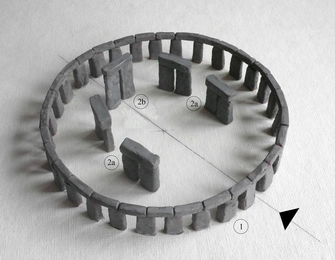
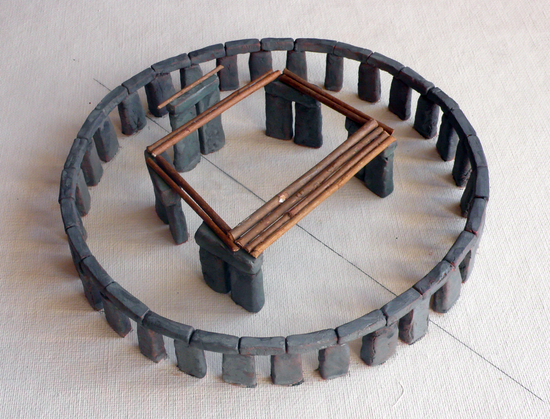
Elements such as 36 and 150 are shaped like lintels and do not match the other bluestone elements. They likely came from a different, older structure. Due to their size and position, the bluestone pillars and sarsen elements could not have functioned structurally together (Fig. 3). Thus, their original purpose remains unclear, though they may have had an additional function.
Sarsen Elements
The sarsen elements were installed after the first bluestone groups in the so-called Sarsen Phase [15]. They dominate the site with their size and weight (up to about 40 tons) and feature unique shapes and joints, distinguishing them from other British megalithic structures.
There are two types of sarsen elements—uprights and lintels—whose dressed forms correspond to columns and beams, the basic building components of more complex structures from later periods [10, 11]. The uprights and lintels primarily carried vertical loads, while the lintels also acted as horizontal ties, stabilizing the structure.

Altar Stone
The Altar Stone was likely an element located on the axis between the Great Trilithon (GT) and the centre of the Stone Monument. Currently broken and partially buried, its original orientation – standing or lying – remains uncertain [5, 6, 16]. However, if it stood upright, it would have been illuminated by sunlight on both solstice days.
Supporting a Roof
The groups SC and SH originally consisted of 75 stones in six basic shapes (Fig. 4). Three of these basic shapes were uprights (with 1a and 5 being atypical) and three were lintels. Generally, the elements of each type were uniform, differing only in size, tenons, and surface dressing.
Sarsen Circle
2b – great trilithon GT ©František Hájek
This circle comprised 30 uprights and 30 lintels, almost regularly arranged in a circular shape (Fig. 5). The rationale for the number 30 and its specific arrangement is not yet fully understood. By utilising the features of the uprights and lintels, along with their methods of interconnection, the stones formed a cylindrical, multi-element enclosure with apertures.

Fig. 6 Interlocking joints: upright – lintel, lintel – lintel ©František Hájek
The above-ground parts of the uprights were similar, with two hemispherical tenons on their upper surfaces interlocking with the lintels (Fig. 6). Except for upright 16, the inner faces of the uprights were vertical and smooth, while the other sides tapered slightly upwards. This shape not only created an optical illusion but also enhanced stability and facilitated construction. Differences in shape primarily resulted from variations in cross-sectional areas and, therefore, differences in vertical load-bearing capacity.
The bearing capacity was greatest at the main northeast entrance and decreased progressively, with the uprights becoming clearly slimmer as the the distance from the entrance increased (Fig. 7). This pattern corresponded to a gradual reduction in the distance between the SC and the trilithons, i.e. between the supports of a possible timber-framed roof. Such a reduction would have decreased the load on the supporting uprights, further suggesting the existence of a roof.
Upright 16 (of type 1a) was extended bilaterally at the base (Fig. 4, 16). Such a shape would have been particularly effective in resisting horizontal forces, which suggests it was positioned beneath a skylight where the Great Trilithon (GT) was located. It is likely that the adjacent fallen and damaged upright 15 had a similar shape and purpose.

The bases of the uprights had varied shapes, ranging from oval to pointed. The Stone Monument was built in geologically suitable conditions, with bedrock located just below the ground surface. The favourable chalk rock allowed the uprights to be set directly into chalice-shaped sockets.
The type 2 lintels had rectangular cross-sections, following the curvature of SC, and featured two mortises on the underside as well as tongue-and-groove joints on their vertical faces. These joints prevented the uprights from tilting and limited the rotation of the lintels. The resulting lintel ring formed a reinforcing structure that secured both the uprights and the lintels themselves [8, 9]. The resulting structure, with its horizontal upper surface of lintels, would have been capable of supporting a significant vertical load from a roof with inclined roof joists.
Sarsen Horseshoe
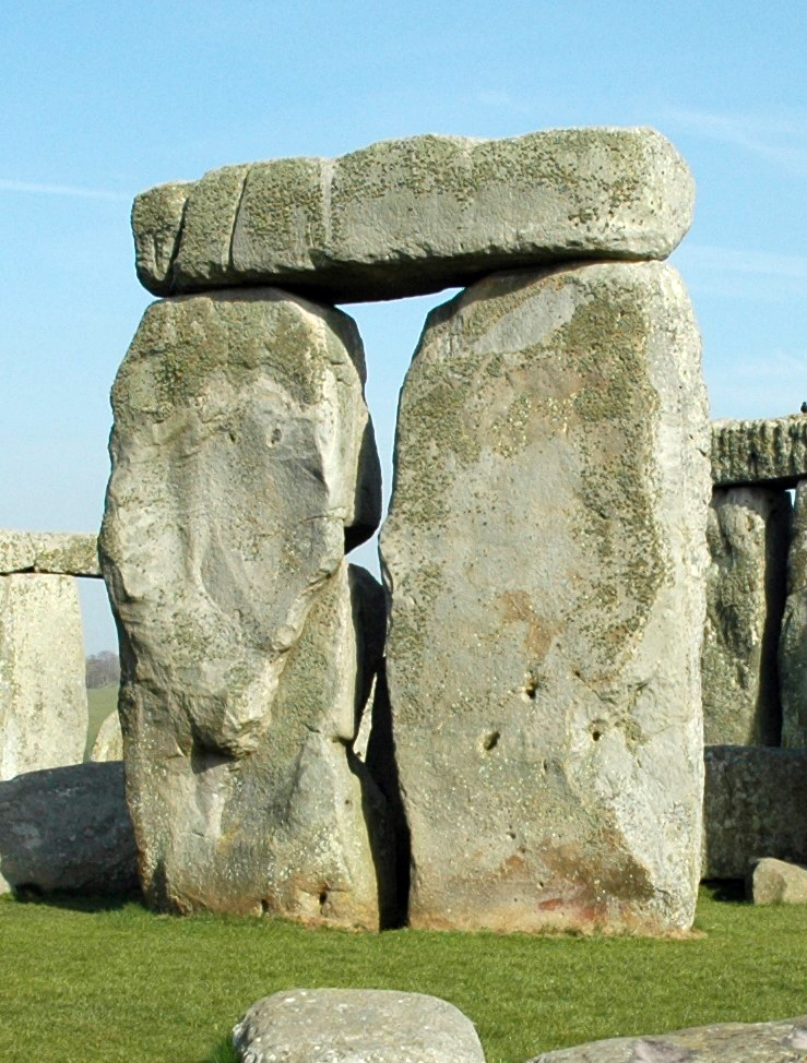
This group consisted of five free-standing trilithons (Fig. 8) – pairs of uprights standing close together and connected by a lintel – arranged in a horseshoe shape open towards the main entrance. Four of these trilithons were positioned in the centre of the interior space, while one, the Great Trilithon, stood apart along the axis (Fig. 5).
The Great Trilithon is the most remarkable and enigmatic of all the stones (Fig. 4, 9). Its location and shape are unusual, standing as the tallest structure, featuring type 5 uprights with vertical outer faces and smooth, worked surfaces on both sides. Only one of its uprights remains standing. The probable original orientation of its outer faces aligned with the longest sides of the Rectangle of Station Stones, which determined the outermost positions of the moonrise and moonset as observed on the horizon [17, 18].
Despite being the tallest, the GT had thinner uprights that widened at the base, indicating that it was expected to bear less vertical load but a greater horizontal load.
The four other trilithons, featuring type 3 uprights, were shorter (Fig. 4) but, at the same time, the largest in the monument. Their uprights were taller than those of the SC, and their lintels were tapered, being wider at the top (Fig. 19). These massive load-bearing uprights and lintels formed highly stable inner supports. This layout was advantageous both structurally and functionally.
Sarsen Circle and Sarsen Horseshoe
As a whole, SC and SH were constructed as load-bearing structures, suggesting they supported a roof. Their height arrangement also corresponded to the shape of a roof, with SC providing peripheral support and the four lower trilithons of SH providing central support. The GT supported a local skylight that allowed for additional illumination (Fig. 16). If the skylight had not been intended, and the GT had no other purpose beyond supporting it, its presence would have been unnecessary.

As individual groups, SC and SH could not have served any other function. The idea that the lintels merely secured the uprights and that the uprights or trilithons did not serve a load-bearing function is illogical. If they were not meant to support anything, why would they be so massive? Given the immense effort required for transport, it seems unlikely that the sheer size of the stones lacked structural significance.
Neither older nor contemporary archaeological literature mentions the load-bearing function of SC and SH. However, the validity of this feature has been scientifically demonstrated in a renowned engineering journal [10].
For SC and SH to function as a roof support, they must have been constructed in a single phase. The positioning of their elements, the process of erecting the individual stones, and the management of the excavated earth suggest that construction could only have taken place on an area cleared of bluestones, which must have been temporarily removed and later reinstalled. Additionally, a pre-built access road would have been required for the transport of the massive stones.
The structural properties of SC and SH created a circular, dual-space enclosure consisting of a central oval and a surrounding peripheral circle, including the main entrance (Fig. 10). Both parts were well-connected visually, acoustically, and communicatively due to the wide gaps between the trilithons. The central part, particularly the inner surfaces of the trilithons, may have held greater significance, as they were more finely worked and better illuminated.
Reconstructing the Roof
Although SC and SH are not completely preserved, the extent of their structural features is enough to proceed with a historically feasible reconstruction of the roof [8, 10]. The roof’s design takes into account the load-bearing, spatial, shape, and aesthetic features of the stone construction as well as the technology available during the assumed construction period. Only simple tools such as stone hammers, boulders, axes, deer antlers, and fire were considered.

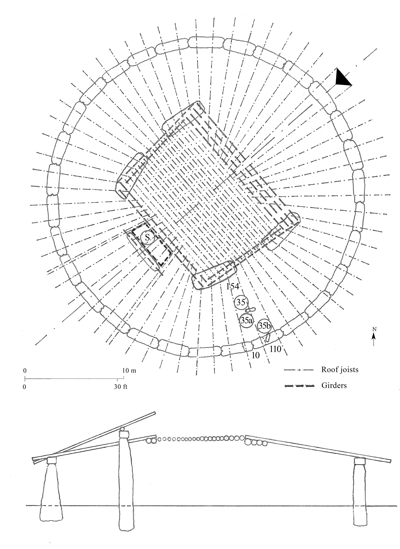
The design of a roof structure would have been determined by the shape of the SC and SH. The roof is assumed to be a simple timber structure with only logs used for its joists and girders. The peripheral horizontal support consisted of SC lintels and the inner supports were additional wooden girders along the lintels of the four lower trilithons (Fig. 11). The roof joists in the central part would run horizontally and unidirectionally, while in the peripheral part, they would be radial and sloped (Fig. 12). The inclination of the central part could be achieved with a lightweight sloped grid structure or a soil layer. A slightly inclined turf roof was chosen for the proposed reconstruction, resulting in a robust yet structurally and technologically simple roof with a skylight that perfectly matched the properties of the stone supporting structure. The shape of a globular canopy (Fig. 13) can be compared to older monuments like the tombs in Newgrange and Knowth in eastern Ireland.

The Destruction Phase
The current state of the Stone Monument raises questions about the causes of its destruction. Analysis suggests that despite differences in foundation depths, footings, and cross-sectional areas, the stones were designed to be stable, even featuring a peripheral stone ring. However, various construction details and their execution resulted in weaknesses that must have eventually led to the collapse.
Destruction of Pillars BC with Recorded Stumps
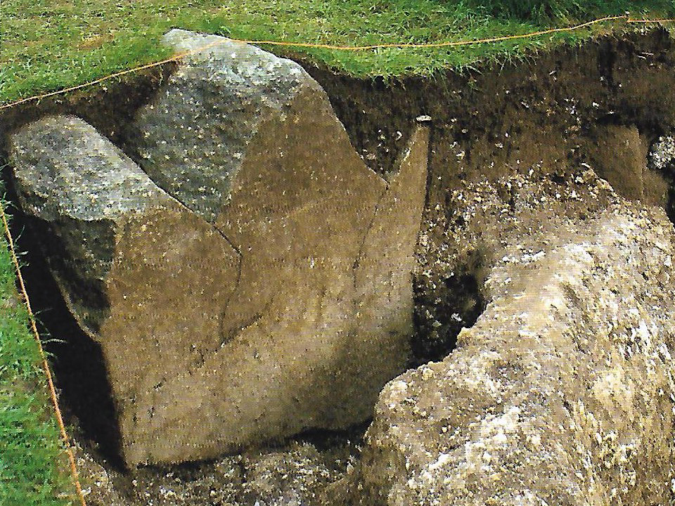
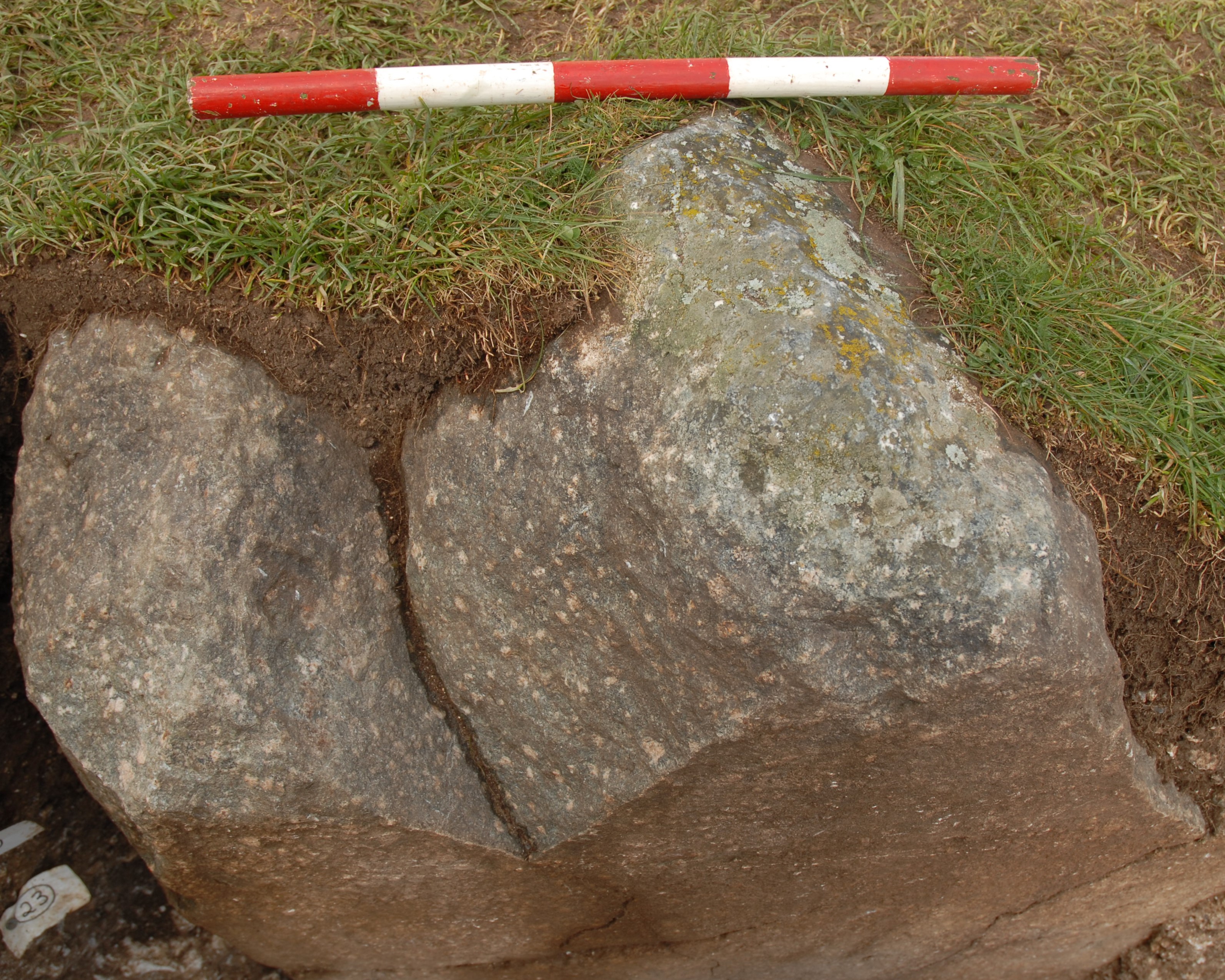
In 2008, during excavations conducted by T. Darvill and G. Wainwright [12], stump 35a, buried in its original position, was uncovered (Fig. 14, 15). Its upper part, 35b, lies partly buried in the ground a few metres further away by the peripheral upright 10 (Fig. 2, 16). The related article [12] states that the damage to the stump is typical of medieval stone theft. Similarly considered in [15]. However, from the shape of the fracture surface of stump 35a, the two vertical fissures, and the positions of the fragments of the pillar, it is evident that it was fractured by a sudden, single impact of a very heavy object from the direction of the trilithons of SH 53, 54 and 154. Such destruction, resulting in two fragments distant from each other, could not have been caused by hand tools, such as a stone hammer.
Similar failures, likely due to the same cause, can be observed in the broken pillars 33, 40, 41, 42, 61, and 70. In the case of the stumps 32 c, d, and f, the cause of their considerable failure cannot be identified from the available picture [19]. However, the destruction of pillar 35 could only have been caused by the fall of a heavy roof structure. Therefore, when assessing the destruction of the Stone Monument, the existence of a roof should be considered. For this assessment, the shape determined by the historical reconstruction was used.
Other Damage and Destruction of Pillars BC
The collapse of the roof onto the pillars had varying results (Fig. 2), [6, 15, 20] such as the:
- toppling of pillars 32, 36, 43, 44, 45, and 150 and possibly, their horizontal dislocation,
- destruction of several pillars’ upper ends – 33, 41, 61, and 70,
- damaged tops – pillars 31, 37, 46, 47, and 62,
- damaged edges, e.g. pillar 49,
- tilting e.g. pillars 41, 46, 47, 61, and 62.
Additional destruction of pillars 38, 39, 40, 66, 67, 68 and 71 occurred due to the collapse of upright 55 and lintel 156 of the GT, or upright 69.
Displacement and Destruction of Peripheral Uprights SC
Seventeen uprights have survived as built, including those that may have been straightened [5, 6, 15], of which:
- one (11) was severely damaged from above and is also leaning outwards,
- three (21, 22, and 23) had fallen outwards and have subsequently been re-erected,
- ten (1, 2, 4, 5, 6, 7, 27, 28, 29, and 30) were leaning and subsequently straightened and stabilised,
- three (3, 10, and 16) remained undisturbed.
Of the remaining uprights:
- five (13, 17, 18, 20, and 24) are missing,
- six (8, 9, 12, 19, 25, and 26) have fallen outwards and
- two (14, and 15) have fallen inwards.
From the damage observed, it is evident that outward tilting and lateral dislocation were the most frequent types of damage the perimeter uprights suffered, as manifested in 18 existing uprights. Such a number represents damage of a general nature. This may have been caused by one or a combination of the following (the top one being the most effective):
- the circular shape of SC and inclined roof joists supported on the lintels’ edge producing outward radial forces pushing the stones outwards,
- water run-off from the roof causing waterlogging of the ground on the outside of the uprights,
- some of the outer faces of foundation holes being lower as a result of the erection process [6, 15] and the back-fill consisting of less suitable (more deformable) chalk rubble.
It appears that the builders were likely aware of these potential effects on SC and had attempted to stabilise the uprights with the peripheral ring [9]. However, the observed damage has shown that, over time, neither the peripheral ring, nor some of the uprights were effective in maintaining the structural integrity of the Stone Monument.

2 – destruction due to excessive tilting or fall of the peripheral lintel SC110
(his supporting upright SC9 has also fallen) ©František Hájek
It is also clear that the slimmer uprights, designed for a lesser vertical roof load, were not sufficiently massive and therefore, over time, not stable enough to resist the radial forces to which they were subjected. This is why they could fall in their original position – for example, upright 12. This also may explain the greater number of missing or destroyed uprights in the southwestern part of the SC.
As the uprights and hence the peripheral roof joints tilted, the support surface for joists was gradually reduced until the heavy joists fell (Fig. 17). If there was any bluestone pillar underneath, it would have been damaged or even destroyed by the ensuing collapse (pillar 35 and the others mentioned above). The collapse of the heavy joists could easily have caused the destruction of the perimeter uprights and their displacement, as shown by the position of uprights 8, 9, 19 and 25.
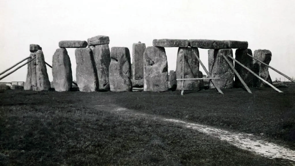
The fact that the uprights were leaning in the past is evident from historical photographs (Fig. 18) and [6, 15], featuring additional support for the uprights 1, 2, 6, 7, 29 and 30. The widths of the openings between the lintels suggest that they may have corresponded to the lateral tilting of the uprights’ tops by up to approximately 0.5 m. Once the critical angle was reached, a collapse of the roof was inevitable.

©František Hájek
There is archaeological evidence that the general horizontal tilting of the uprights’ tops was already evident to the people using the monument. The mysterious Y and Z holes around the perimeter of the SC are explained as evidence of the placement of additional structural support for the uprights (Fig. 19). The number of holes corresponds to the number of uprights and their connecting lines would have been correctly oriented to act as a reinforcement against the visible structural deformation. They are concentric but in an irregular way. The distances between the holes and the SC elements are not uniform, so their position does not indicate a structural relationship to each other. The shape of the holes corresponds to that of a support structure. For this reason, it can be argued that the holes were not the last evolutionary stage of Stonehenge, as is commonly perceived, but a manifestation of a rescue attempt to save the main structure. The failure on the top edge of pillar 28 (Fig. 20) also points to the existence of stabilising support.

Water Damage
The green roof would not have been completely waterproof. Tilting of the uprights and roof joists could also compromise the integrity of the roof covering. Water penetration, over an extended period, would have led to the gradual degradation of the wooden roof structure, which could have caused a collapse. Falling roof joists would have collided with the uprights, causing some of the failures and dislocations visible today. This type of destruction is evident in fallen uprights 8, 9, 12, 19, 25, and 59 and lintels 120 and 160. The collapse of the trilithon 57, 58 and 158, in turn, points to the gradual tilting due to one-sided soil waterlogging.
Wind Damage
The highest uprights of the monument, the Great Trilithon, which would have supported the skylight, the upright 55 and lintel 156, fell inward, while upright 56 remains significantly leaning. Also, both uprights 14 and 15 of the SC fell inwards. This was possibly due to the effects of wind. Despite appearing to consider wind effects when designing the GT, its construction and that of its skylight did not adequately withstand wind loads or ensure positional stability over time.
Vandalism
Some damage on the edges of elements appears to be the result of the activities of souvenir collectors, characterized by localised splitting at the lower corners of standing elements or accessible edges of lying elements, distinguishing them from damage to the tops of uprights and pillars, which could have resulted from the roof’s collapse.
Conclusions
This structural engineering assessment of the Stone Monument and its destruction revealed the following key findings:
- The Stone Monument was delineated based on the Rectangle Station Stones and in all likelihood replicates its astronomical properties.
- Stonehenge consists of three types of megalithic stones, each serving different functions: sarsen stones (group SC and SH), bluestones (group BC and BH), and Altar Stone.
- Unlike other British Neolithic structures, the elements of SC and SH were deliberately shaped, interlocked, and constructed according to a pre-defined architectural design.
- SC and SH exhibit all the characteristics of roof-supporting structures and define the layout of the building.
- The existence of a roof is further evidenced by the observed damage and destruction patterns of sarsen uprights and bluestone pillars.
From an archaeological perspective, no remains of the fallen roof have been found – likely because the timber either decayed over time or was repurposed. However, the structural engineering evidence strongly indicates its existence.
The structural evidence is compelling enough to conclude that the Stone Monument was originally a roofed building. It was circular and two-roomed, with a wooden roof likely shaped as an irregular spherical cap with a skylight. This roof would have protected its occupants from rain while allowing for astronomical observations on the horizon. The building was highly sophisticated and unique for its time. Compared to the wooden houses of that area, its complexity was as significant as the difference between modern multi-story buildings and skyscrapers. Given its remarkable features, it had the potential to be the most prominent structure on Salisbury Plain, warranting the title of the Central Building of the Stonehenge landscape.
It is highly likely that the positioning of this roofed structure at the center of the enclosure was intentional and played a significant role in Stonehenge’s overall function and significance. The rearranged and newly situated bluestones within SC and SH suggest continuity with the site’s earlier use as a cemetery. Professor M. Parker Pearson has suggested that Stonehenge was primarily a site dedicated to death, with the bluestone pillars serving as monuments of remembrance for ancestors [5].
However, considering the building’s weather protection, shape, capacity, astronomical alignment, interior aesthetics, and natural illumination, it is arguable that the Central Building of Stonehenge was also a place for the living. This could have included year-round tracking of the sun and moon’s extreme positions, particularly the solstices, as well as related ceremonial events. Another possibility, based on the astronomical properties of SC and SH, is T. Darvill’s hypothesis that Stonehenge functioned as a solar calendar [14], continuously marking time throughout the year. Given these factors, the roofed structure was likely multi-purpose.
It is important to note that none of these activities would have been hindered by the presence of a roof. However, the true purpose of this extraordinary structure remains an open question, one that will require further research, including structural analysis, to be fully understood.
Acknowledgements
The author would like to thank Mr Antony Johnson – (Fig. 2), Mr Mike Pitts – (Fig. 15), Professor Timothy Darvill – (Fig. 16) for the permission to use their pictures, Mr John Nicholson for translation and comments on the text, and my daughter, Ms Karla Hanzlová, for her help with the graphics.
Postscript
This structural engineering assessment, which explores the possibility of a roofed Stonehenge, is an independent initiative by the author and has not received any grant funding. This research has been published at the author’s own expense. The paper was previously submitted to several British archaeology journals but was met with a lack of interest, likely due to the prevailing belief that Stonehenge never had a roof.
This reluctance may reflect a paradox within British archaeology, where roofed structures are recognized when postholes and floor remains are present — but where a monument with clear structural characteristics of a roof-supporting system is not recognised.
The idea that Stonehenge was roofed challenges conventional assumptions, and while further research is needed, the structural evidence presented in this paper makes a strong case for reconsidering its original form and function.
Bibliography
[1] Van de Pradene, A: The Use of Wood in Megalitic Structures, Antiquity 1937
[2] Carter, G: Twelve reasons why Stonehenge was a building, 2012. http://structuralarchaelogy. blogspot.cz/2012/03/twelve-reasons-why-stonehenge-was.html
[3] Bedlam, B: Why would it not have a roof? www.stonehenge.tv/roof.html. 04/2017
[4] Ewbank, S: Sunhenge – Stonehenge had a Roof. http://sunhenge.uk, 04/2017
[5] Parker Pearson, M.: Stonehenge, a brief history. Bloomsbury Academic. London 2023
[6] Johnson, A.: Solving Stonehenge, Thames & Hudson Ltd, London, 2008
[7] https://en.wikipedia.org/wiki/Stonehenge: Stonehenge
[8] Hájek, F.: Stonehenge bola stavba so strechou. Bol to chrám? (Stonehenge – a building with a roof, was it a temple?), Stavebnictví 04/2015
[9] Hájek. F: Stonehenge – najstaršia stavba s obvodovým ťahadlom (Stonehenge – the oldest structure with a peripheral tie), Beton 6/2015
[10] Hájek. F: Was Stonehenge a roofed Temple? The Structural Engineer, 05/2017
[11] Hájek, F: Stonehenge bol pretrešený objekt. Statické posúdenie historickej kamennej stavby. (Stonehenge was a roofed structure. Static assessment of the historical stone building). Beton 4/2023
[12] Darvill, T, Wainwright, G: Stonehenge excavations 2008. The Antiquaries Journal 89, 2009
[13] Darvill, T, Marshall, P, Pearson M. Parker, Wainwright, G: Stonehenge remodeled, Antiquity 86, 2012: pp. 1021-40
[14] Darvill T: Keeping time at Stonehenge. Antiquity, 96, 2022, pp. 319-335
[15] Pitts, M: How to build Stonehenge? Thames & Hudson Ltd, London, 2022
[16] Parker Pearson, M, Richard Bevins, Richard Bradley, Rob Ixer, Nick Perce, Colin Richards: Stonehenge and its Altar Stone: the significance of distant stone sources, Archaeology international, 27(1), 113-137, 2024
[17] Rükl, A.: Stonehenge, in Kozmické rozhledy 2, 1967, Neperiodický věstník Československé astronomické společnosti při ČSAV (Non-periodical Journal of the Czechoslovak Astronomical Society at the Czechoslovak Academy of Sciences), Praha, pp. 34 – 43
[18] http://www.thebritisacademy.ac.uk: Ruggles C., Astronomy and Stonehenge, Proceedings of the British Academy, 92, 203 – 229
[19] http://www.English-heritage.org.uk: Early excavations and survey. Read more about Stonehenge’s early archaeologists, Research on Stonehenge.
[20] http://www.stoneofstonehenge.org.uk/: Banton, S: The Stones of Stonehenge
This is an Open Access article, distributed under the terms of the Creative Commons Attribution-NonCommercial-ShareAlike 4.0 International License (CC BY-NC-SA 4.0), which permits non-commercial use, distribution, and reproduction in any medium, provided the original work is properly cited and shared under the same license.


